6-Layer Rigid-Flex PCB for Car Tracker GPS Applications
(FPC’s are custom-made products, the picture and parameters shown are just for reference)
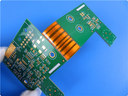
Introducing Our 6-Layer Rigid-Flex PCB for Car Tracker GPS
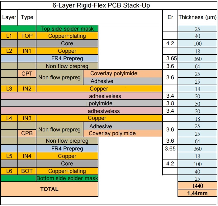
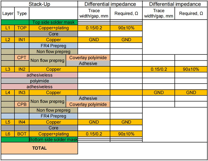
We are excited to introduce our 6-layer rigid-flex printed circuit board (PCB), specially engineered for car tracker GPS applications. This high-performance PCB features a thickness of 1.4mm, combining half-ounce copper on the inner layers and one ounce on the outer layers. With an impedance-controlled design on both the outer layers and the inner flexible circuit, this PCB is built to meet the rigorous demands of modern electronics.
PCB Specifications
| Size of Flexible PCB | 120.61 X 50.17mm |
| Number of Layers | 6 |
| Board Type | Rigid-flex PCB |
| Board Thickness | 1.44mm |
| Board Material | FR-4 / Polyimide |
| Board Material Supplier | Shengyi |
| Tg Value of Board Material | 170℃ |
| PTH Cu thickness | ≥20 µm |
| Inner Iayer Cu thicknes | 18 µm |
| Surface Cu thickness | 35 µm |
| Coverlay Colour | Yellow coverlay / Green solder mask |
| Number of Coverlay | 2 |
| Thickness of Coverlay | 25 µm |
| Stiffener Material | N/A |
| Stiffener Thickness | N/A |
| Type of Silkscreen Ink | IJR-4000 MW300 |
| Supplier of Silkscreen | TAIYO |
| Color of Silkscreen | White |
| Number of Silkscreen | 1 |
| Peeling test of Coverlay | No peelable |
| Legend Adhesion | 3M 90℃ No peeling after Min. 3 times test |
| Surface Finish | Immersion Gold |
| Thickness of Surface Finish | Au: 0.03µm(Min.); Ni 2-4µm |
| RoHS Required | Yes |
| Famability | 94-V0 |
| Thermal Shock Test | Pass, -25℃±125℃, 1000 cycles. |
| Thermal Stress | Pass, 300±5℃,10 seconds, 3 cycles. No delamination, no blistering. |
| Function | 100% Pass electrical test |
| Workmanship | Compliance with IPC-A-600H & IPC-6013C Class 2 |
Key Features and Advantages
Superior Flexibility: This design provides excellent flexibility, making it suitable for applications requiring intricate routing and compact spaces.
Volume Reduction: The innovative structure allows for a significant reduction in overall volume, facilitating easier integration into devices.
Weight Savings: Lightweight construction without compromising durability is a key advantage of our design.
Consistent Assembly: Ensures uniformity in assembly, leading to improved reliability in performance.
Enhanced Reliability: With immersion gold plating on pads, our PCB supports reliable surface mount technology (SMT) assembly.
Cost-Effective Solutions: Enjoy low-cost options with no minimum order quantity, making it easier for businesses to prototype and scale.
Timely Delivery: We maintain an impressive on-time delivery rate of over 98%, ensuring your projects stay on schedule.
Applications
Our versatile 6-layer rigid-flex PCBs are ideal for a variety of applications, including:
Contact belts for inkjet printers
Industrial surveying and mapping instruments
Tablet PC camera soft boards
Manufacturing Processes
The manufacturing process for our rigid-flex PCBs includes several key steps, illustrated in the simplified flow diagram provided.
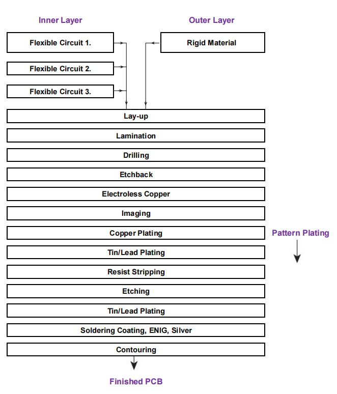
Flexible Inner Layers
The inner layers are crafted as single- or double-sided flexible circuits through a consistent imaging, etching, and covering process, without drilling or plating. This method minimizes the risk of air entrapment, although it requires an additional step for covercoating.
Flexible sections can be bonded together, simplifying the process but resulting in relative rigidity, limiting the bend cycles to a maximum of 25. Alternatively, leaving flexible circuits unbonded allows for a staggered build-up, which can prevent buckling while bending the circuit into position; however, this adds complexity to manufacturing.
Rigid Outer Layers
For the outer layers, rigid materials like FR-4 are cut to size and bonded during the lamination process. This can be managed as a temporarily rigid board to facilitate easier handling during production and assembly. To ensure that rigid outer layers do not bond to flexible areas, both sides of the flexible section are covered with release films. Non-bonded portions of the rigid material can be removed using a snap-action technique, provided that grooves are cut at the interfaces prior to lamination.
